Introduction to the Spanning Tree Protocol | Configuring | Verifying and Troubleshooting
Figure 1.0
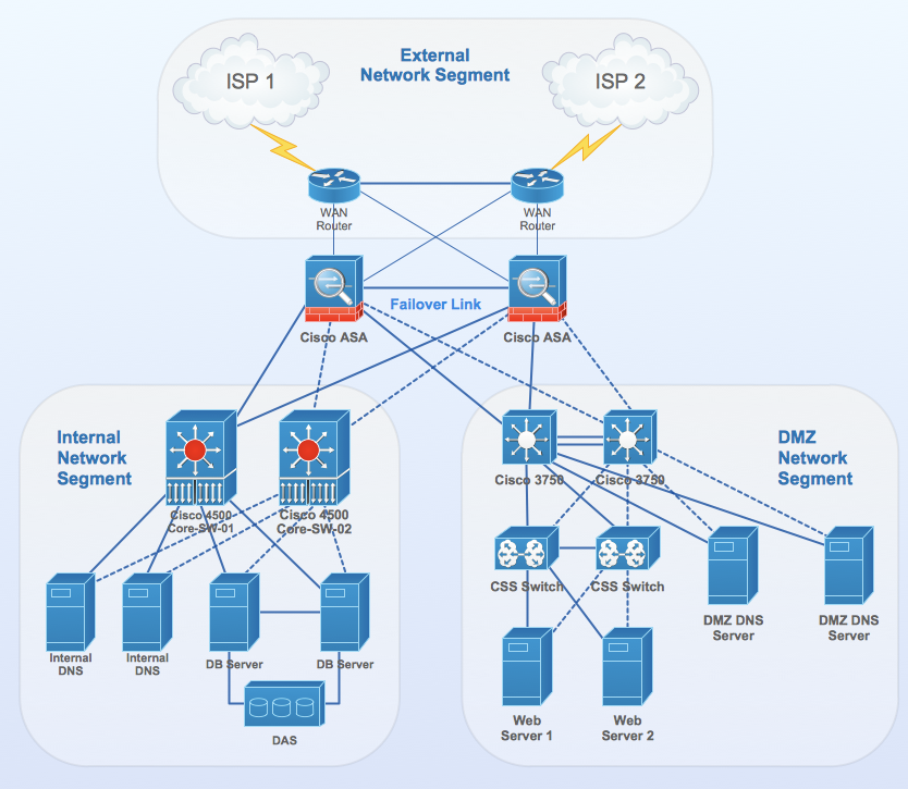
Modern networks require redundancy to preserve business continuity as the consumption of networked-based resources are in the greatest demand in our century more than any other as we have become internet oriented. Our over reliance on internet technology only means that our servers, business and web applications must be constantly available and accessible, hence the need for a redundant network design to address these keen needs.
STP, otherwise known as the Spanning Tree Protocol (802.1D) was invented to maintain Redundant Networks without incurring loops on the network as broadcasts are channeled in the right optimal paths. Spanning Tree Protocol uses a clever mechanism or algorithms to create this loop free network by doing the following. This unique algorithm computes the optimum loop-free path through a switched Layer 2 network by assigning a role to each port based on the role of the port in the active topology:
- Root—A forwarding port elected for the spanning-tree topology
- Designated—A forwarding port elected for every switched LAN segment
- Alternate—A blocked port providing an alternate path to the root bridge in the spanning tree
- Backup—A blocked port in a loopback configuration
Spanning-Tree Interface States
Switches LANs can experience propagation delays with protocol information passing through the network and as a result, topology changes can occur at different times and at different points or locations on the switched network. An interface transitioning directly from non-participation in the spanning-tree topology to a forwarding state can create temporary data loops which could cause issues on the network. Interfaces therefore must wait for current topology information to propagate through the switched LAN before beginning to forward frames (BPDUs). They must allow the frame lifetime to expire for forwarded frames that have used the old topology.
Each Layer 2 interface on a switch using spanning tree exists in one of these states:
- Blocking—The interface does not participate in frame forwarding.
- Listening—The first transitional state after the blocking state when the spanning tree decides that the interface should participate in frame forwarding.
- Learning—The interface prepares to participate in frame forwarding.
- Forwarding—The interface forwards frames.
- Disabled—The interface is not participating in spanning tree because of a shutdown port, no link on the port, or no spanning-tree instance running on the port.
An interface moves through these states:
- From initialization to blocking
- From blocking to listening or to disabled
- From listening to learning or to disabled
- From learning to forwarding or to disabled
- From forwarding to disabled
Electing the Root Bridge or the Reference Switch of the Topology:
The election is made based on the Bridge Priority which by default for all switches is 32768. The BID is customisable but when the election becomes a tie due to the Switches’ Bridge Priority being the same for example Switch A# BID 32768 and Switch B# BID 32768, then the selection is now based on the Mac Address of the Switches.
The Switch with the lowest Mac Address becomes the Root Bridge on the network. The idea behind the use of the lowest Mac Address is due to the fact that, aged switches on the network are likely to know and maintain a CAM Tsble which is indepth than a newly introduced switch to the network. If on the other hand, the Root Bridge is failing and you have been tasked to replace it, then you will have to bring in a switch whose Bridge Priority is lower.
Manually Change the Bridge Priority
 SWITCH-A(config)#spanning-tree vlan 1 priority 24576
SWITCH-A(config)#end
SWITCH-A#
%SYS-5-CONFIG_I: Configured from console by console
Verify Manually Configured Priority and Root Bridge Status
SWITCH-A#show spanning-tree
VLAN0001
  Spanning tree enabled protocol ieee
  Root ID    Priority    24577
             Address     00D0.5877.63C5
             This bridge is the root
             Hello Time  2 sec  Max Age 20 sec  Forward Delay 15 sec
This Switch becomes the Reference Point for the maintaining of a Loop FreeNetwork as the switches now makes decisions with this reference in mind.
Root Bridges sets their directly connected ports to Designated Forwarding Ports meaning that it s available for transactions to and from.
Figure 1.1 – Diagram of Root Bridge Ports in Designated Forwarding Mode
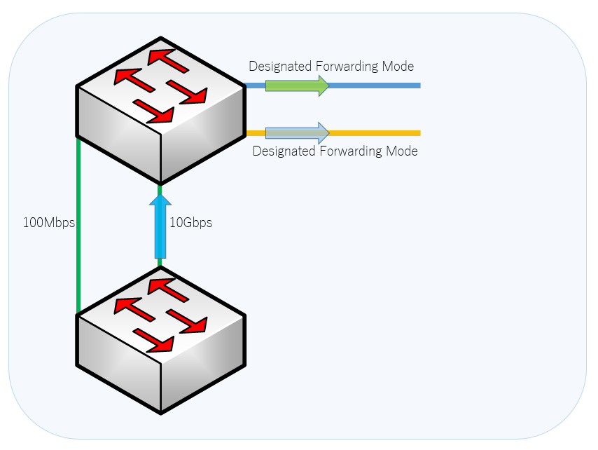
Every Non-Root Bridge selects only one path to the Root Bridge based on the cost of the link. The path cost
- 10 Gbps link cost is 2
- 1 Gbps link cost is 4
- 100 MB link cost is 19
- 10 MB link cost is 100
Figure 1.2 – Diagram of Non Root Bridge Ports Connecting to the Root Bridge based on costs
Feature |
Default Setting |
| Enable state | Enabled on VLAN 1. |
| Spanning-tree mode | PVST+. (Rapid PVST+ and MSTP are disabled.) |
| Switch priority | 32768. |
| Spanning-tree port priority (configurable on a per-interface basis) | 128. |
| Spanning-tree port cost (configurable on a per-interface basis) | 1000 Mb/s: 4.
100 Mb/s: 19. 10 Mb/s: 100. |
| Spanning-tree VLAN port priority (configurable on a per-VLAN basis) | 128. |
| Spanning-tree VLAN port cost (configurable on a per-VLAN basis) | 1000 Mb/s: 4.
100 Mb/s: 19. 10 Mb/s: 100. |
| Spanning-tree timers | Hello time: 2 seconds.
Forward-delay time: 15 seconds. Maximum-aging time: 20 seconds. Transmit hold count: 6 BPDUs |
It is important to note the following when troubleshooting STP problems.
Switches forward broadcast packets out all ports by design
Redundant connections are necessary in business networks
How STP Finds the Best Path
- Elect the Root
- Find the Best Path to the Root
- Lowest Cost
- Lowest Bridge ID
- Lowest Port Number
- Block whatever is left over.
What could go wrong in real networks?
- Mac Address Flapping /Broadcast Storm
- Temporary Portfast Loop (Short Duration)
- BPDU Filter/Root Guard Incorrectly Applied
- Wrong Root Bridge Elected
- Misconfiguration (Such as Etherchannel, Native Vlan).
Spanning Tree Verification and Troubleshooting Commands
    show spantree vlan_id
    show spantree summary
    show spantree statistics
    show spantree backbonefast
    show spantree blockedports
    show spantree portstate
    show spantree portvlancost
    show spantree uplinkfast
show spantree vlan_id —Shows the current state of the spanning tree for this VLAN ID, from the perspective of the switch on which you issue the command.
show spantree summary —Provides a summary of connected spanning tree ports by VLAN.
show spantree statistics —Shows spanning tree statistical information.
show spantree backbonefast —Displays whether the spanning tree BackboneFast Convergence feature is enabled.
show spantree blockedports —Displays only the blocked ports.
show spantree portstate —Determines the current spanning tree state of a Token Ring port within a spanning tree.
show spantree portvlancost —Shows the path cost for the VLANs on a port.
show spantree uplinkfast —Shows the UplinkFast settings.