To design and build a two-tier campus network architecture is everything like a three-tier hierarchical design and maximizes performance, network availability, and the ability to scale the network design. It is common to campus networks where the aggregation or distribution layer is merged with the core layer to create a unique and fully functional network for a good sized campus.
However, many small enterprise networks do not grow significantly larger over time. Therefore, a two-tier hierarchical design where the core and distribution layers are collapsed into one layer is often more practical. A “collapsed core” is when the distribution layer and core layer functions are implemented by a single device. The primary motivation for the collapsed core design is reducing network cost, while maintaining most of the benefits of the three-tier hierarchical model..
To design and build a two-tier campus network architecture, a number of considerations must be taken into account. A key head-start is to ascertain the driver for choosing to build a two-tier campus network architecture.
Could it be a preferred design or one which you know works well and easily maintained? Perhaps you found yourself working in an environment which had their design closely tailored to the tier-2 collapsed core hierarchy.
Before we get into designing and building our two-tier campus network architecture and this article could end up being a series as the content is extensive. If you are already familiar with the background to hierarchical design, scroll down to the configuration for the respective tiered-layers.
Cisco puts a good narrative on the need for a Structured Network Design and as per an excerpt – Read the full document here: Cisco Networking Academy Connecting Networks Companion Guide: Hierarchical Network Design
Structured Engineering Principles
Regardless of network size or requirements, a critical factor for the successful implementation of any network design is to follow good structured engineering principles. These principles includeHierarchy: A hierarchical network model is a useful high-level tool for designing a reliable network infrastructure. It breaks the complex problem of network design into smaller and more manageable areas.
Modularity: By separating the various functions that exist on a network into modules, the network is easier to design. Cisco has identified several modules, including the enterprise campus, services block, data center, and Internet edge.
Resiliency: The network must remain available for use under both normal and abnormal conditions. Normal conditions include normal or expected traffic flows and traffic patterns, as well as scheduled events such as maintenance windows. Abnormal conditions include hardware or software failures, extreme traffic loads, unusual traffic patterns, denial-of-service (DoS) events, whether intentional or unintentional, and other unplanned events.
Flexibility: The ability to modify portions of the network, add new services, or increase capacity without going through a major forklift upgrade (i.e., replacing major hardware devices).
To meet these fundamental design goals, a network must be built on a hierarchical network architecture that allows for both flexibility and growth.
Design and Build a Two-Tier Campus Network Architecture

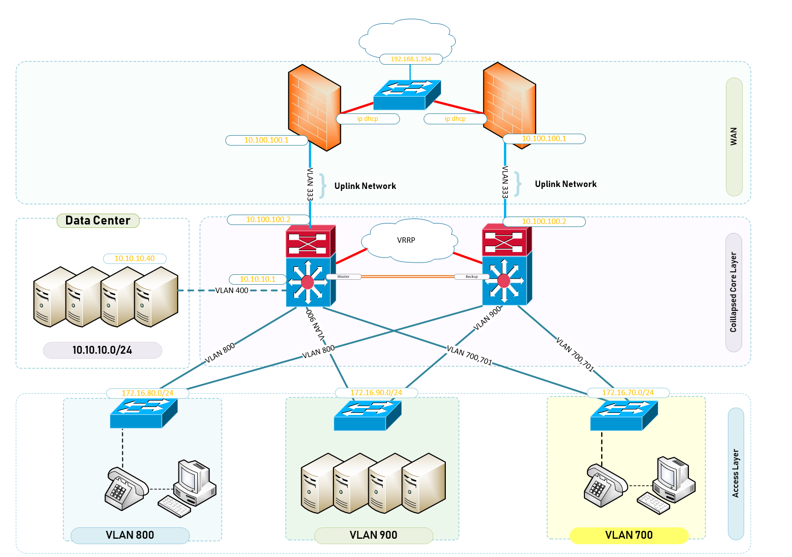
Your campus has a number of buildings which are on a completely flat network and things are not working as they should. You have been tasked with redesigning the entire network infrastructure making sure that each building has a dedicated VLAN and that all those VLANS are allowed on the Internet. You start to think of the expert way in designing your network based on the budgets and equipment available for this requirement. The following list is a break down of what you inherited as a network engineer.
Access
The well loved access layer is located on the first tier or edge of the campus. It is the location where end devices (PCs, printers, cameras, and the like) attach to the wired portion of the campus network reside. It is additionally a place where devices that extend the network out one more level are attached— IP or VOIP Phones and wireless access points (APs) being the most common two key examples of devices that extend the connectivity out one more layer from the actual campus access switch. The wide variety of possible types of devices that can connect and the various services and dynamic configuration mechanisms that are necessary, make the access layer one of the most feature-rich parts of the campus network.The access layer intelligently provides the demarcation required between the network infrastructure and the computing devices that leverage that infrastructure. As such it provides a security, QoS, and policy trust boundary. It is the first layer of defense in the network security architecture and the first point of negotiation between end devices and the network infrastructure. When looking at the overall campus design, the access switch provides the majority of these access-layer services and is a key element in enabling multiple campus services.
Distribution
The distribution layer in the campus design has a unique role in that it acts as a services and control boundary between the access and the core. Both access and core are essentially dedicated special purpose layers. The access layer is dedicated to meeting the functions of end-device connectivity and the core layer is dedicated to providing non-stop connectivity across the entire campus network. The distribution layer on the other hand serves multiple purposes. It is an aggregation point for all of the access switches and acts as an integral member of the access-distribution block providing connectivity and policy services for traffic flows within the access-distribution block. It is also an element in the core of the network and participates in the core routing design.Its third role is to provide the aggregation, policy control and isolation demarcation point between the campus distribution building block and the rest of the network. Going back to the software analogy, the distribution layer defines the data input and output between the subroutine (distribution block) and the mainline (core) of the program. It defines a summarisation boundary for network control plane protocols (EIGRP, OSPF, Spanning Tree) and serves as the policy boundary between the devices and data flows within the access-distribution block and the rest of the network. In providing all these functions the distribution layer participates in both the access-distribution block and the core. As a result, the configuration choices for features in the distribution layer are often determined by the requirements of the access layer or the core layer, or by the need to act as an interface to both. The function of the distribution layer is discussed in more detail in the description of the access-distribution block and the associated design sections.
Core
The campus core is in some ways the simplest yet most critical part of the campus. It provides a very limited set of services and is designed to be highly available and operate in an always-on mode. In the modern business world, the core of the network must operate as a non-stop 7x24x365 service. The key design objectives for the campus core are based on providing the appropriate level of redundancy to allow for near immediate data-flow recovery in the event of any component (switch, supervisor, line card, or fiber) failure. The network design must also permit the occasional, but necessary, hardware and software upgrade/change to be made without disrupting any network applications. The core of the network should not implement any complex policy services, nor should it have any directly attached user/server connections. The core should also have the minimal control plane configuration combined with highly available devices configured with the correct amount of physical redundancy to provide for this non-stop service capability.The core campus is the backbone that glues together all the elements of the campus architecture. It is that part of the network that provides for connectivity between end devices, computing, and data storage services located within the data center—and other areas and services within the network. It serves as the aggregator for all of the other campus blocks and ties together the campus with the rest of the network. One question that must be answered when developing a campus design is this: Is a distinct core layer required? In those environments where the campus is contained within a single building—or multiple adjacent buildings with the appropriate amount of fiber—it is possible to collapse the core into the two distribution switches.
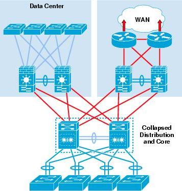
It is essential to consider that in any campus design even those that can physically be built with a collapsed distribution core that the primary purpose of the core is to provide fault isolation and backbone connectivity. Isolating the distribution and core into two separate modules creates a clean delineation for change control between activities affecting end stations (laptops, phones, and printers) and those that affect the data center, WAN or other parts of the network. A core layer also provides for flexibility for adapting the campus design to meet physical cabling and geographical challenges. As an example, in a multi-building campus design like that shown in Figure 3, having a separate core layer allows for design solutions for cabling or other external constraints to be developed without compromising the design of the individual distribution blocks. If necessary, a separate core layer can use different transport technology, routing protocols, or switching hardware than the rest of the campus, providing for more flexible design options when needed.
Multi-Building Campus Network
- ASA Firewalls x2
- Core Switches x2 | VRRP Core Switches
- Access Switches x32 | Access Layer Switches for Buildings
- Fibre Inter-Connections to Buildings A and Building B.
Equipment Used;
- Cisco ASA ASA5506-x;
- Sonic Wall NSA 220 : Same Configuration as Cisco ASA Firewall
- HPE Aruba Core – Layer 3 Switch
- HPE Aruba Access Switch – Multiple VLANS
- HPE Aruba Access Switch – Single VLANS
Configuration – Design and Build a two-tier campus network architecture – WAN Layer
I like to work from Outside-In for many reasons of which one is the ability to test connectivity to the internet as I gradually slip into the WAN and LAN Networks.
In this article, I shall begin with breaking down the network topology into 3 important parts.
- WAN Layer
- Collapsed Core | Aggregation or Distributionand Core Layer
- Access Layer