Would you like to stretch your layer two network across your inter-site links for the purposes of replication and intercluster services? If that is the case then “Using VXLAN to Extend L2 Networks Across Layer 3 Links” could well be the best option to get you going.
Scenario:
HQ(Site A) has a dedicated 10Gbps leased link to DR(Site B). As a network engineer, you have been asked to take advantage of the speed and capacity of the inter-site link to extend capabilities of storage systems, backups and replications to the DR site which is Site B. You have been asked to stay away from traditional vlans and ensure the interlink is purely Layer-3 with no possibility of VLANS spanning across to the other site.
OTV is an IP-based functionality that has been designed from the ground up to provide Layer 2 extension capabilities over any transport infrastructure: Layer 2 based, Layer 3 based, IP switched, label switched, and so on. The only requirement from the transport infrastructure is providing IP connectivity between remote data center sites. In addition, OTV provides an overlay that enables Layer 2 connectivity between separate Layer 2 domains while keeping these domains independent and preserving the fault-isolation, resiliency, and load-balancing benefits of an IP-based interconnection.
With OTV you can deploy virtual computing resources and clusters across geographically distributed data centers, delivering:
- Transparent workload mobility
- Business resiliency
- Superior computing resource efficiencies
VXLAN (Virtual extensible LAN ) an open IETF specification designed to standardise an overlay encapsulation protocol, capable of relaying layer-2 traffic over IP networks.
Using VXLAN to Extend L2 Networks Across Layer 3 Links
Aruba has some recommended steps for configuring VXLAN Tunnels
The base requirement for the above topology and use case is a VXLAN: (VXLAN uses the UDP Port 4789 by default). The RFC7438 might be a good read in your spare time. Let’s get right into it.
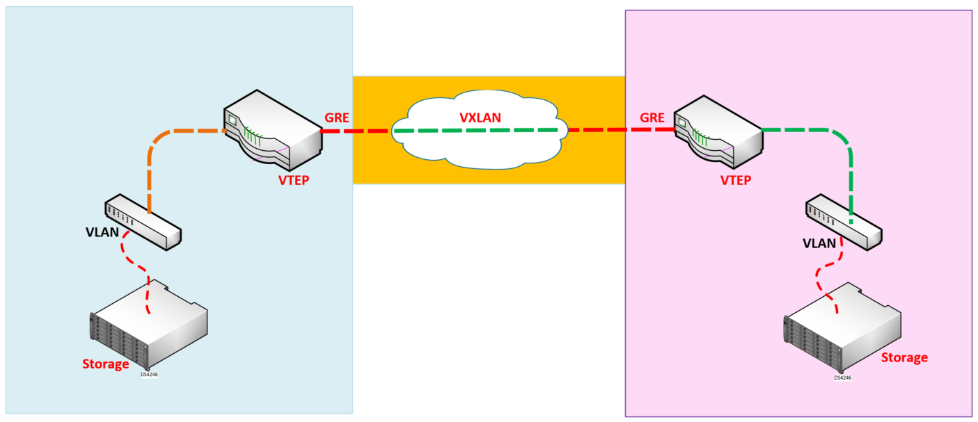
VXLAN is an overlay technology that extends Layer 2 VLANS across a Layer 3 IP Network. It creates a Layer 2 Tunnel also called a VXLAN Segment between 2 Virtual Tunnel Endpoints also known as VTEP.
VXLAN (Virtual Extensible LAN) – The technology that provides the same Ethernet Layer 2 network services as VLAN does today, but with greater extensibility and flexibility.
VNID (Vxlan Network Identifier) – 24 bit segment ID that defines the broadcast domain. Interchangeable with “VXLAN Segment ID”.
VTEP (Virtual Tunnel Endpoint) – This is the device that does the encapsulation and de-encapsulation.
NVE (Network Virtual Interface) – Logical interface where the encapsulation and de-encapsulation occur.
What is VXLAN?
VXLAN is a technology which allows overlaying a Layer 2 (L2) network over a Layer 3 (L3) underlay with use of any IP routing protocol. It uses MAC-in-UDP Encapsulation.
VXLAN solves three main problems:
- 16M VNIs (broadcast domains) versus the 4094 offered by traditional VLANs.
- Allows L2 to be extended anywhere in an IP network.
- Optimized flooding.
Why VXLAN?
- VLAN Scalability – VXLAN extends the L2 Segment ID field to 24-bits, which potentially allows up to 16 million unique L2 segments over the same network.
- L2 Segment Elasticity over L3 Boundary – VXLAN encapsulates an L2 frame in an IP-UDP header, which allows L2 adjacency across router boundaries.
- Leverages multicast in the transport network in order to simulate flooding behavior for broadcast, unknown unicast, and multicast in the L2 segment.
- Leverage Equal Cost Multi-pathing (ECMP) in order to achieve optimal path usage over the transport network.
Figure 1.2 | Overlay Network(VXLAN) and Underlay Network (VTEP)
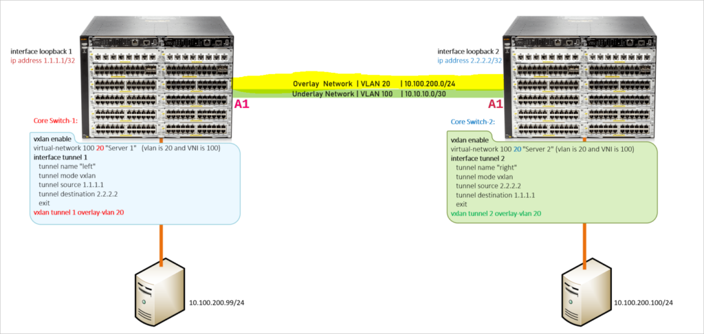
Below is the existing configuration for Point-to-Point Interlink between the Core Switches
Core Switch 1: Interface A1
Core-1#

interface A1
   name "10GB Interlink Leased Link"
   untagged vlan 100
   exit
Core-1#
Core Switch 2: Interface A1
Core-2#
interface A1
   name "10GB Interlink Leased Link"
   untagged vlan 100
   exit
Core Switch 1: Interface Configuration
Core-1#
vlan 100
   name "Intersite Leased 10 Gbps Pipe"
   untagged A1
   ip address 10.10.10.1 255.255.255.252
   ip ospf 10.10.10.1 area backbone
   ip ospf 10.10.10.1 network-type point-to-point
   exit
Core-1#
Core Switch 2: Interface Configuration
Core-2#
vlan 100
   name "Intersite Leased 10 Gbps Pipe"
   untagged A1
   ip address 10.10.10.2 255.255.255.252
   ip ospf 10.10.10.2 area backbone
   ip ospf 10.10.10.2 network-type point-to-point
   exit
Core-2#
A VTEP performs these two roles:
Receive Layer 2 traffic from a source, such as a VM, in an Ethernet broadcast domain, encapsulating it within a VXLAN frame and sending it to the destination
VTEP. Receive the VXLAN frame, stripping the encapsulation to reveal the encapsulated Ethernet frame, and forwarding the frame toward the destination included in the encapsulated Ethernet frame.
VXLAN tunnel which carries the encapsulated data is called an overlay network.
The IP physical network that switches and routes the tunnels that make up the overlay is called the underlay network.(This is your traditional network, mostly your existing vlans and trunks.)
Configuration Steps:
- Disable v2 modules
- Enable VXLAN
- Create a Virtual-network (VNI) and associate a vlan
- Create a Vxlan tunnel and define source and destination VTEP’s
- Map the tunnel to a overlay network
Cannot create a Virtual Network when the switch is in compatibility mode. The compatibility mode can be disabled by executing the [no] allow-v2-modules command.
Core Switch-1: Configure a loopback interface for the tunnel’s source.
interface loopback 0
ip address 1.1.1.1
Enable VXLAN – Disallow V2 Modules(Will not work with allowed v2 modules)
no allow-v2-modules
vxlan enable
Configure Virtual Network Interface (VNI)
virtual-network 100 20 "Server 1" (vlan is 20 and VNI is 100)
Configuring GRE Tunnels and VXLAN for VLAN Overlays
interface tunnel 1
   tunnel name "Server-1 Network"
   tunnel mode vxlan
Specify the source and destination of the tunnel:
   tunnel source 1.1.1.1
   tunnel destination 2.2.2.2
   exit
Overlay Tunnel with VLAN 20
vxlan tunnel 1 overlay-vlan 20
Configure Static Route towards Tunnel Loopback Interface on Core B
ip route 2.2.2.2 255.255.255.255 10.10.10.2
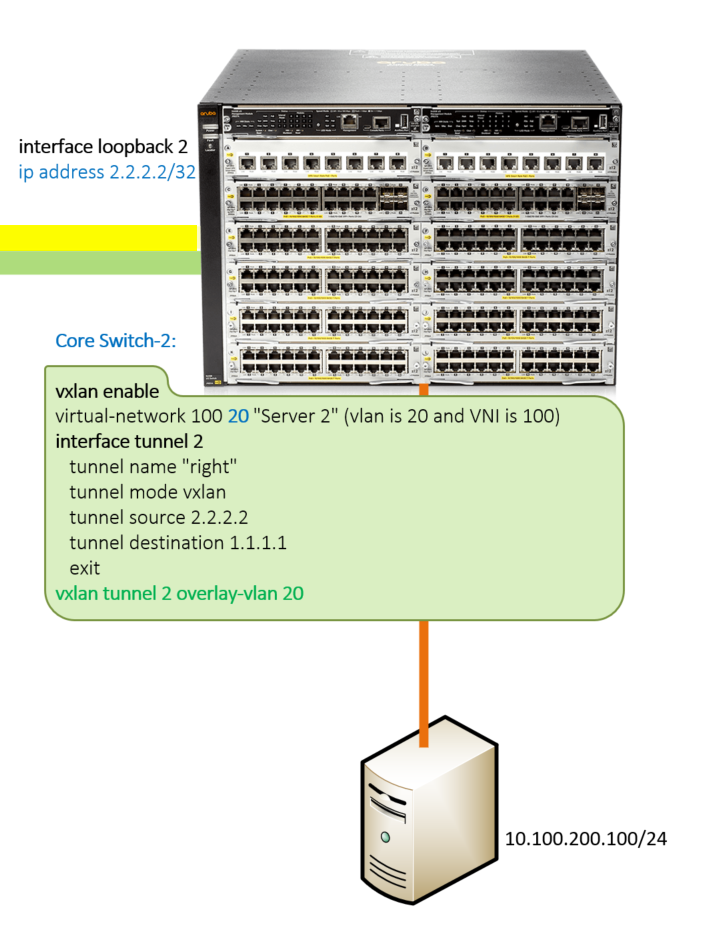
Core Switch-2:Configure a loopback interface for the tunnel’s source
interface loopback 0
ip address 2.2.2.2
Enable VXLAN - Disallow V2 Modules(Will not work with allowed v2 modules)
no allow-v2-modules
vxlan enable
Configure Virtual Network Interface (VNI)
virtual-network 100 20 "Server 2" (vlan is 20 and VNI is 100)
Configure Tunnel Interface
interface tunnel 2
   tunnel name "Server-2 Network"
   tunnel mode vxlan
Specify the source and destination of the tunnel:
   tunnel source 2.2.2.2
   tunnel destination 1.1.1.1
   exit
Overlay Tunnel with VLAN 20
vxlan tunnel 2 overlay-vlan 20
Configure Static Route towards Tunnel Loopback Interface on Core A
ip route 1.1.1.1 255.255.255.255 10.10.10.1
Verify Tunnel Interface States
Core-1# show interfaces tunnel brief

 Status - Tunnel Information Brief


  Tunnel                   : 251659490
  Mode                     : VXLAN Tunnel
  Source Address           : 1.1.1.1
  Destination Address      : 2.2.2.2
  Configured Tunnel Status : Enabled
  Current Tunnel State     : Up

Core-1#
Core-1# show interfaces tunnel

 Tunnel Configuration :

  Tunnel               : 251659490
  Tunnel Name          : VXLAN_Tunnel01
  Tunnel Status        : Enabled
  Source Address       : 1.1.1.1
  Destination Address  : 2.2.2.2
  Mode                 : VXLAN Tunnel
  TOS                  : -1
  TTL                  : 64
  IPv6                 : n/a
  MTU                  : 1450


 Current Tunnel Status :

  Tunnel State              : Up
  Destination Address Route : 2.2.2.2/32
  Next Hop IP               : 10.10.10.2
  Next Hop Interface        : vlan-10
  Next Hop IP Link Status   : Up
  Source Address            : 1.1.1.1


Core-1#
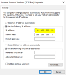
Server Configuration for Server 1:
Ethernet adapter Ethernet 1:

   Connection-specific DNS Suffix  . : expertnetworkconsultant.com
   Link-local IPv6 Address . . . . . : fe80::8051:832b:99:60c7%20
   Link-local IPv6 Address . . . . . : fe80::ab47:d863:23d2:5ffd%20
   IPv4 Address. . . . . . . . . . . : 10.100.200.99
   Subnet Mask . . . . . . . . . . . : 255.255.255.0
   Default Gateway . . . . . . . . . : ::
Server Configuration for Server 2:
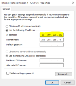
Ethernet adapter Ethernet 1:

   Connection-specific DNS Suffix  . : expertnetworkconsultant.com
   Link-local IPv6 Address . . . . . : fe80::8051:832b:99:60c7%20
   Link-local IPv6 Address . . . . . : fe80::ab47:d863:23d2:5ffd%20
   IPv4 Address. . . . . . . . . . . : 10.100.200.100
   Subnet Mask . . . . . . . . . . . : 255.255.255.0
   Default Gateway . . . . . . . . . : ::
Perform Verification:
Core-Switch-1(config)# show interfaces tunnel 1
 Tunnel Configuration :

  Tunnel               : 251659491
  Tunnel Name          : Storage Server 1
  Tunnel Status        : Enabled
  Source Address       : 1.1.1.1
  Destination Address  : 2.2.2.2
  Mode                 : VXLAN Tunnel
  TOS                  : -1
  TTL                  : 64
  IPv6                 : n/a
  MTU                  : 1280
Core-Switch-1# show interfaces tunnel type vxlan statistics 251659490
  Tunnel Name                                  : Storage Server 1
  Rx Packets                                   : 0
  Tx Packets                                   : 0
  Rx 5 Minute Weighted Average Rate (Pkts/sec) : 0
  Tx 5 Minute Weighted Average Rate (Pkts/sec) : 0
Core-Switch-2:
Core-Switch-2# show interfaces tunnel 2
 Tunnel Configuration :

  Tunnel               : 251659491
  Tunnel Name          : Storage Server 2
  Tunnel Status        : Enabled
  Source Address       : 2.2.2.2
  Destination Address  : 1.1.1.1
  Mode                 : VXLAN Tunnel
  TOS                  : -1
  TTL                  : 64
  IPv6                 : n/a
  MTU                  : 1280
Core-Switch-2# show interfaces tunnel type vxlan statistics 251659491
  Tunnel Name                                  : Storage Server 2
  Rx Packets                                   : 0
  Tx Packets                                   : 0
  Rx 5 Minute Weighted Average Rate (Pkts/sec) : 0
  Tx 5 Minute Weighted Average Rate (Pkts/sec) : 0
Core-Switch-2:
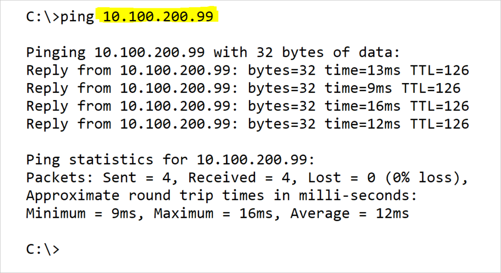
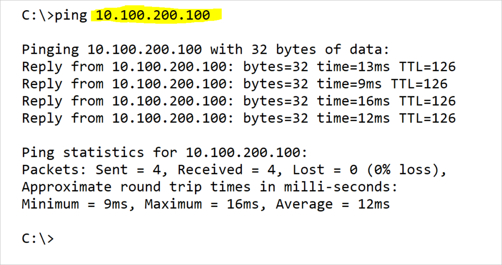
Now that you are satisfied with the configuration of both tunnels, let us test connectivity between Server-1 and Server-2.
Applications:
Storage Replications to DR Site(s). Imagine your HQ has a 10Gbps link to another site which serves as the Disaster Recovery Site. NetApp SnapMirror® for example replicates between sites. Sometimes, the link between the sites may be a routed link which will not permit the extension of a layer 2 vlan across. Creating a Tunnel tied with a VXLAN ensures that the NetApp SnapMirror® would work over layer 2 as an overlay over the routed inter-site link.
Download Cisco VXLAN Document BRKDCT-2404
Microsoft has an excellent article which applies to Hyper-V over VXLAN technology which I find might be a good read for you.
The next steps will be to secure the point to point GRE over IPSEC. Ciso has a good article on Point-to-Point GRE over IPSEC which is a good read.
More Cisco OTV Resources.
Some useful Cisco VXLAN Labs
