So what is Inter-VLAN Routing?
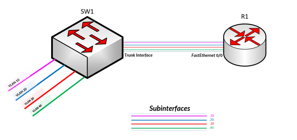
Traditionally, most small businesses have users connected via a Switch in one Broadcast Domain (see Figure 1.0 above) which enables all devices on the network to speak with each other. It is a simple defacto but not the best approach if you have departments and wants their dealings to be contained in their logical space. Logical because, with VLANS, a number of interfaces on the switch which represents the users end devices or host machines are grouped logically so they are independent and securely contained away from unexpected broadcasts(announcements).

Scenario
Ruby works in the Production(VLAN 10) and needs Caleb who works in Marketing(VLAN 20) to pick up an important publication first thing on Tuesday morning. Suzy has just realised that the Publication Printer is in the Marketing Department and due to the sensitive nature of the document, she only wants to print the relevant pages and so cannot it to Caleb.
She then decides to get the IT guy to give her access to the Printer in the Marketing department. The Network guy says to Ruby, there seem to be a problem! The departments are not allowed to speak with each other. Ruby then says, do something about this, I need to be able to print these documents by close of day so Caleb can have it shipped first thing in the morning.
Do Something About It!
Well, the Network Guy says leave that with me and he performs Inter-VLAN Routing using Routing on a Stick per the steps below.

Create an IP Addressing Scheme for each VLAN’s Subnet.
VLAN 10 = 10.10.10.0/24
VLAN 20 = 10.10.20.0/24
VLAN 30 = 10.10.30.0/24
VLAN 40 = 10.10.40.0/24
Create IP Addressing Scheme for each Subinterface on Router

FastEthernet 0/0.10 =10.10.10.10/24
FastEthernet 0/0.20 = 10.10.20.20/24
FastEthernet 0/0.30 = 10.10.30.30/24
FastEthernet 0/0.40 = 10.10.40.40/24
Expected Configuration required on Router
Encapsulation dot 1q {vlan ID}
Subinterfaces on interface configured on router for respective VLANS
interface fastethernet 1/0/0.1
encapsulation dot1q 10 {example of configuration under the subinterface}
ip address subnet mask
enable interface
Expected configuration required on Switch
Configure Trunk interface to the Router
Interfaces for respective Vlans
Switchport mode for interfaces
Step 1 > Configure Trunk Interface FastEthernet0/0 on Switch
SW1(config)#int fa0/1
SW1(config-if)#switchport mode trunk
SW1(config-if)#exit
Step 2 > Enable interface FastEthernet on Router
R1(config)#int fa0/0
R1(config-if)#no ip address
R1(config-if)#no shutdown
R1(config-if)#exit
Step 3 > Configue the respective VLANS on SW1
SW1(config)#int fa0/10
SW1(config-if)#switchport mode access
SW1(config-if)#switchport access vlan 10
SW1(config-if)#exit

SW1(config)#int fa0/20
SW1(config-if)#switchport mode access
SW1(config-if)#switchport access vlan 20
SW1(config-if)#exit

SW1(config)#int fa0/30
SW1(config-if)#switchport mode access
SW1(config-if)#switchport access vlan 30
SW1(config-if)#exit

SW1(config)#int fa0/40
SW1(config-if)#switchport mode access
SW1(config-if)#switchport access vlan 40
SW1(config-if)#exit
Step 4 > Configure Ethernet interface for the appropriate subinterfaces;
hostname(config)# interface physical_interface.subinterface for example
hostname(config)# interface gigabitethernet0/1.100
NOTE: the “.” Between the interface ID and the subinterface ID is a requirement. The subinterface ID is a logical number which describes the VLAN ID allowed on that interface.
Let’s start with VLAN’s 10 Subinterface configuration on R1
R1(config)#int fastEthernet 0/0.10
R1(config-subif)#encap
R1(config-subif)#encapsulation  dot1Q 10
R1(config-subif)#ip address 10.10.10.1 255.255.255.0
R1(config-subif)#no shut
Verify configuration to ensure it’s working – repeat for the other subinterfaces;
R1#show int fastEthernet 0/0.10
FastEthernet0/0.10 is administratively down, line protocol is down
  Hardware is Gt96k FE, address is c401.2a6c.0000 (bia c401.2a6c.0000)
  Internet address is 10.10.10.1/24
  MTU 1500 bytes, BW 10000 Kbit/sec, DLY 1000 usec,
     reliability 255/255, txload 1/255, rxload 1/255
  Encapsulation 802.1Q Virtual LAN, Vlan ID  10.
  ARP type: ARPA, ARP Timeout 04:00:00
  Last clearing of "show interface" counters never
You realise that the subinterface has identified its associated VLAN as well as the encapsulation protocol used, in this case being an 802.1Q. See below;
Encapsulation 802.1Q Virtual LAN, Vlan ID 10.
Verify configuration information for the subinterfaces;
R1#show ip int brief
Interface                  IP-Address      OK? Method Status                Protocol
FastEthernet0/0            unassigned      YES unset  administratively down down
FastEthernet0/0.10         10.10.10.1     YES manual administratively down down
FastEthernet0/0.20         10.10.20.1     YES manual administratively down down
FastEthernet0/0.30         10.10.30.1     YES manual administratively down down
FastEthernet0/0.40         10.10.40.1     YES manual administratively down down
Serial0/0                  unassigned      YES unset  administratively down down
FastEthernet0/1            unassigned      YES unset  administratively down down
Serial0/1                  unassigned      YES unset  administratively down down
Whereas Inter-VLAN routing might be a great approach to solving VLAN isolation, there is a considerable amount of points to be aware of. These include the pros and caveats to the use of Inter-VLAN routing.
Port Limits
Physical interfaces are configured to have one interface per VLAN. On networks with many VLANs, using a single router to perform inter-VLAN routing is not possible.
Subinterfaces allow a router to scale to accommodate more VLANs than the physical interfaces permit.
Performance
Because there is no contention for bandwidth on physical interfaces, physical interfaces have better performance for inter-VLAN routing. When subinterfaces are used for inter-VLAN routing, the traffic being routed competes for bandwidth on the single physical interface. On a busy network, this could cause a bottleneck for communication.
Access Ports and Trunk Ports
Connecting physical interfaces for inter-VLAN routing requires that the switch ports be configured as access ports.
Subinterfaces require the switch port to be configured as a trunk port so that it can accept VLAN tagged traffic on the trunk link.
Cost
Routers that have many physical interfaces cost more than routers with a single interface. Additionally, if you have a router with many physical interfaces, each interface is connected to a separate switch port, consuming extra switch ports on the network. Financially, it is more cost-effective to use subinterfaces over separate physical interfaces.
Complexity
Using subinterfaces for inter-VLAN routing results in a less complex physical configuration than using separate physical interfaces. On the other hand, using subinterfaces with a trunk port results in a more complex software configuration, which can be difficult to troubleshoot. If one VLAN is having trouble routing to other VLANs, you cannot simply trace the cable to see if the cable is plugged into the correct port. You need to check to see if the switch port is configured to be a trunk and verify that the VLAN is not being filtered on any of the trunk links before it reaches the router interface.
You also need to check that the router subinterface is configured to use the correct VLAN ID and IP address for the subnet associated with that VLAN.
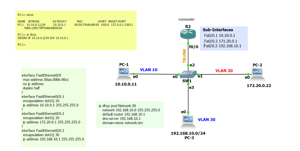
Let’s Lab it all Up
Download GNS3 lab configuration files -> inter-vlan routing gns3 project files
I have used a 7200 Cisco Router, 3 VPCs and the Standard GNS3 EtherSwitch

