Understanding VLANS for CCNP Switch
Are you getting ready to write your CCNP Switch Exams? If so then this article on understanding VLANs for CCNP Switch is worth every moment of your browsing time.
If you are already familiar with VLANs then this article which features how VLANs are used may be useful to you: Inter-VLAN Routing using the concept of Router on a Stick
So what is a VLAN? VLANs are arbitrarily defined broadcast domains because it is not tied directly to a specific port on a switch.
Understanding VLANS for CCNP Switch
Broadcast Domain: Devices, nodes, computers, systems in a Broadcast Domain can see the MAC addresses of other devices in the same broadcast domain. They can communicate with each other by using MAC addresses. But what is the significance in devices being able to see others in the same broadcast domain?
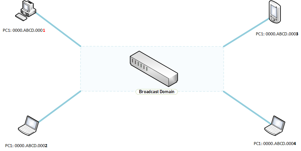
Numerous devices in a broadcast domain could mean excessive flood on the network as the switch will keep flood the network regarding the mac addresses of devices. The best thing for an engineer to do is to reduce the size of broadcast domains to mitigate flooding.
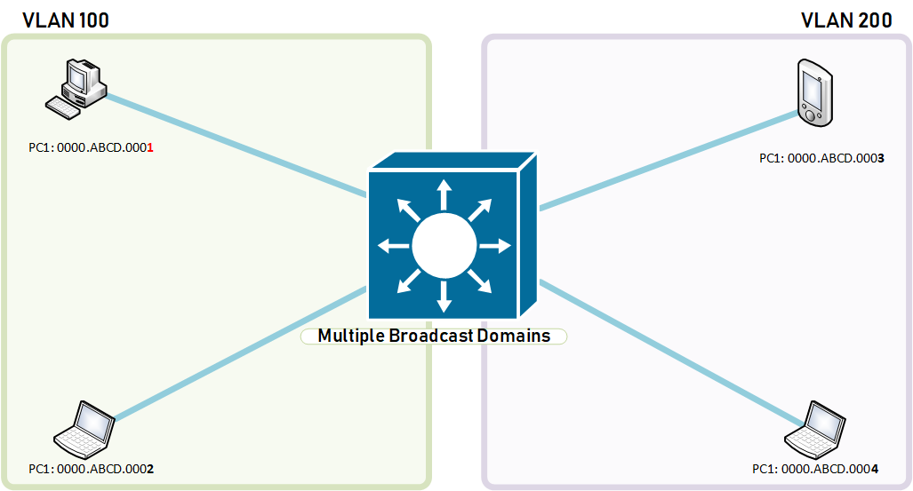
When this segmentation happens, PC1 will not be able to speak with PC4 which means that ethernet frames from PC1 will not get flooded outside its own VLAN because they are in different broadcast domains.
VLAN Identifiers or VLAN Numbers: Switches uniquely identify VLANs using a numerical identifier between 1 and 4094. VLAN 1 comes as a standard on most switches and vulnerable to attacks as they are the default VLANs on most switches. It is best to use different identifiers as a good practice.
Normal VLANs have their VLAN Identifiers from 1 through 1001 and the vlan configuration is stored locally on the Switch’s flash as a VLAN Database called vlan.dat. VLANs 1 through 1001 are not stored in the startup or running configuration. Deleting the startup configuration does not delete normal VLANs. Should you wish to delete all your normal VLANs, type the following commands to do it.
SW1#delete flash:vlan.dat
Understanding VLANS for CCNP Switch
Confirm the action by pressing the enter key.
VLAN 1 is a normal VLAN and comes preconfigured on the Switch. All the interfaces on a switch by default is part of VLAN1. This is the only VLAN you cannot delete or disable. Control Plane traffic rides on VLAN 1 by default.
The likes of Cisco Discovery Protocol are supported by the presence of VLAN 1.


How to configure normal vlans.

SW1(config) #vlan 100
SW1(config-vlan) #name DATA
SW1(config-vlan) #state active
SW1(config-vlan) #end
How to add a port to a VLAN.
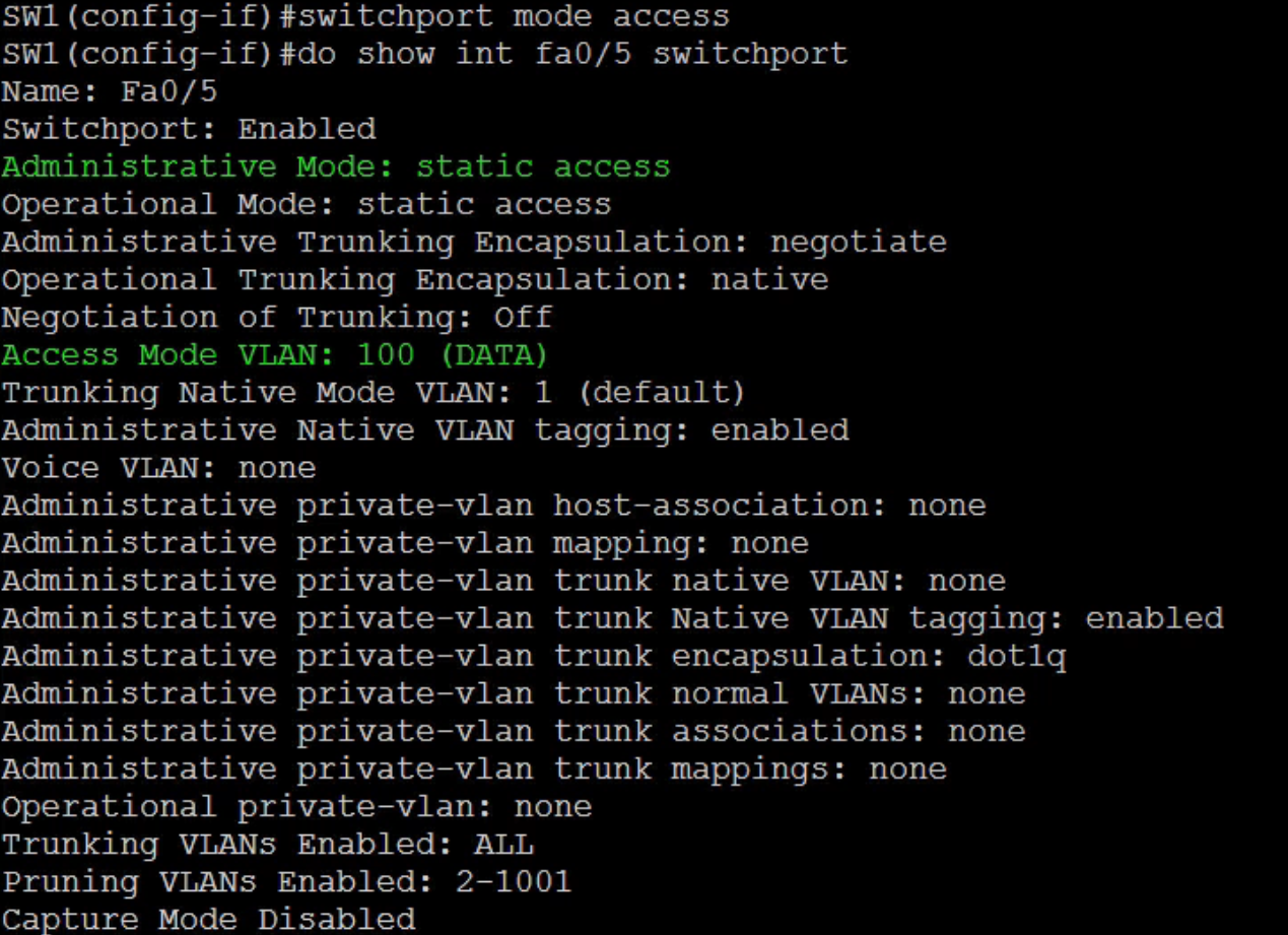
Let’s make interface fa0/5 a member of VLAN 100.
SW1(config) #interface fa0/5
SW1(config-if) #switchport access vlan 100
SW1(config-if) #switchport mode access
SW1(config-vlan) #end
Verify interface status to ensure it has been added to the vlan as required.
SW1(config)#show int fa0/5 switchport
What if you had to add a number of ports, for example interfaces fa0/6-fa0/20?
SW1(config-if) #interface range fa0/6-20
SW1(config-if-range) #switchport access vlan 100
SW1(config-if) #switchport mode access
SW1(config-vlan) #end
Perform a verification for one of the ports
SW1(config)#show int fa0/9 switchport
The switchport mode access command causes the port to become a member of one and only one VLAN.
Configuring Voice VLANs
Instead of having separate wiring for telephony, the same wiring is used for both the voice packets and the data packets. Switches tend to do a lot of flooding and the activity of flooding could affect Voice traffic as they are extremely sensitive. Cisco came up with the Voice VLAN or the Auxiliary VLAN which takes care if you like the quality of services for handling voice traffic to data traffic over the wire.
A few key points to note here is that the Voice VLAN itself is not actually anything special to another. It is created as a normal VLAN and the port configuration is what makes a voice VLAN special. Let’s perform an exercise as per the details below.
On your Switch let’s call it Switch 1: Configure voice VLAN 120 and name it VOICE. Configure FastEthernet0/5-10 to use VLAN120 as the voice VLAN.
Create the VLAN
SW1#
SW1(config)#vlan 120
SW1(config-vlan)#name VOICE
SW1(config-vlan)#state active
SW1(config-vlan)#end
Verify the VLAN created – See screenshot
SW1#show vlan

Now that the VLAN has been successfully created and verified, let’s go ahead to add the ports interfaces fa0/5-10 to the VLAN.
SW1(config) #interface range fa0/5-10
SW1(config-if) #switchport voice  vlan 120
SW1(config-if) #switchport mode access
SW1(config-vlan) #end
Let’s verify if the interfaces are appropriately now in the VLAN as configured.

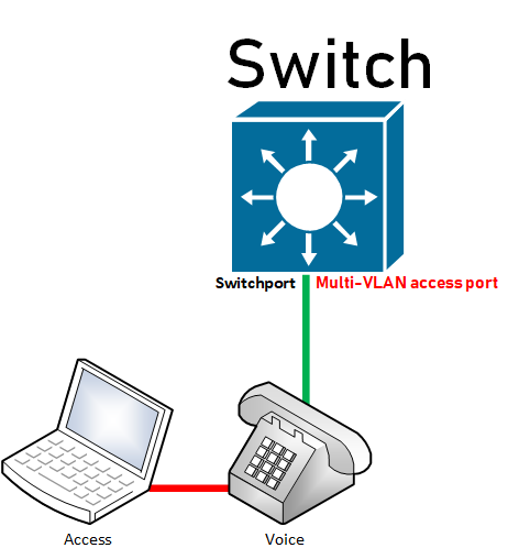 When can an interface become a member of two vlans? We can see that interface fa0/5 has become a member of two VLANs. But did we not say that an interface can only be part of a single vlan and that vlan only? The exception to the rule is when there is a voice vlan. The same interface hosts two devices, a voice and access device which means there must be some clever technology to get each unique device in their appropriate vlans. Hence the Voice VLAN created by Cisco to cater for this important requirement.

But how do you verify from the switch which vlan takes care of which under such special circumstances? You guessed right, yes it is the switchport command we used previously, see below:
SW1(config)#show int fa0/5 switchport
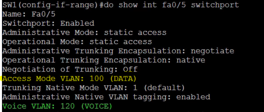
A port with both a static access and voice VLAN configured is called a multi-VLAN access port. Behind the scenes the voice frames going to and from the switch have 802.1q tags. The 802.1q VLAN Tag is 4 bytes in length.
See how an ethernet IEEE 802.3 Frame contains an 802.1q Tag for the voice VLAN?
EthernetIEEE 802.3 Frame

Ethernet IEEE 802.3 Frame Containing a 802.1q Tag for VOICE VLAN
 A multi-VLAN access port can be a member of only the access and voice VLANs.
The Tag ProtocolID is 16 bits
Priority:3 bits
Drop eligible: 1 bit
VLANID: 12 bits
VLANs and Security
There is a lot of talk regarding shutting down VLAN 1 on your switch as all ports are default members of VLAN 1 and since VLAN 1 is one big broadcast domain posses a security concern as there are hackers out there who have tools to attack VLAN1. Although these are all valid, I beg to differ as VLAN 1 has important traffic on the control plane. Dynamic Trunking Protocol and Cisco Discovery Protocol all run on VLAN 1 and so NO, you cannot shutdown VLAN 1 but you can secure it.
VLAN 1 is the default EthernetVLAN and cannot be deleted,renamed, or shut down.
Let’s look at a requirement.
How do you configure Switch SW1 so that layer 2 user traffic does not traverse VLAN1?
The assumption that VLAN 1 can be shutdown and that it then secures the switch from attacks is not exactly correct. The interface VLAN 1 is not VLAN 1, it is the Switched Virtual Interface(SVI) layer 3 interface that lives on VLAN 1.

Shutdown the VLAN

Show Interface VLAN 1
Although we had VLAN 1 shutdown initially, in the screenshot below you still see that the status says it is active.

So what is the best approach?
The best approach is to move the interfaces in the vlan to another vlan. You do so by typing:
SW1(config-if)#interface range fa0/1-24
SW1(config-if-range)#switchport access vlan 100
SW1(config-if-range)#switchport mode access
Let’s verify again what VLAN 1 Interfaces show as;
SW1(config)# show vlan

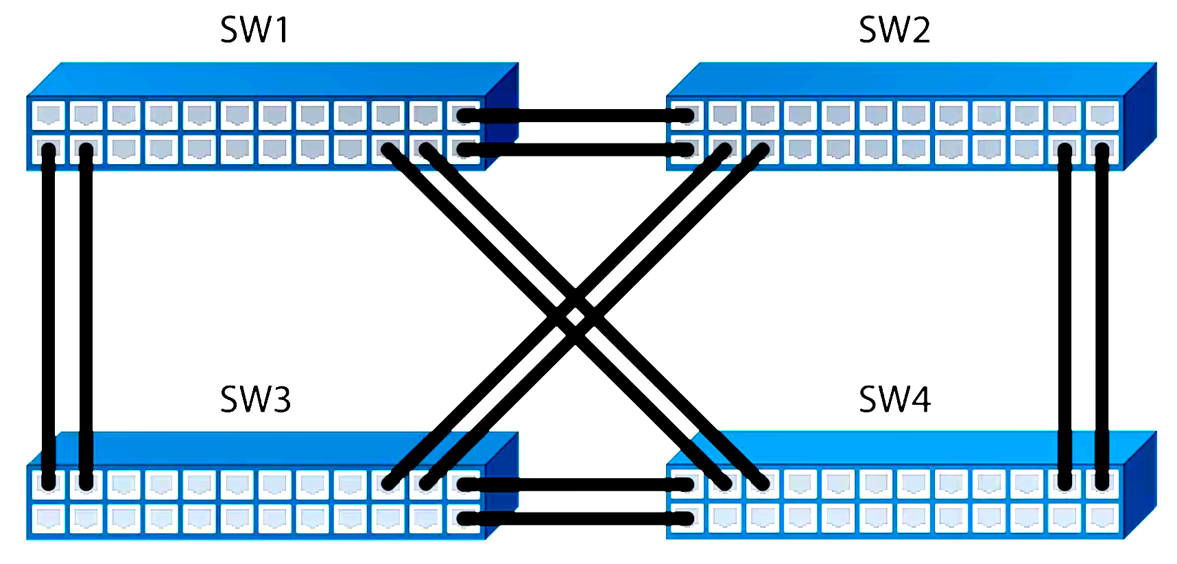
As you can see from the above screenshot, all the fastethernet interfaces have been moved to vlan 100. I deliberately left the GigabitEthernet Interfaces but could easily move them if I so wished. VLAN1 is more secure now that we have VLAN 100. VLAN 100 is an open broadcast domain where any device could communicate to another device via layer 2. We can stop this by using something called Private VLANs.
Private VLANs
Unlike regular VLANs, Private VLANs are designed to restrict traffic between hosts at Layer 2. Restricting traffic here does not necessarily mean blocking it. Private VLANs are defined in the RFC 5517, Cisco Systems’ Private VLANS.
Primary VLANs : These carry traffic from the default gateway to the hosts. This same VLAN identifies the private VLAN domain. A single Primary VLAN can have one or more secondary VLANs.
Secondary VLANS: These could be 1 or 2 VLAN types, Isolated or Community. With Isolated VLANs, hosts cannot communicate at layer 2 but can communicate to the default-gateway. With Community VLANs, hosts can communicate with others hosts but within the same secondary VLAN.
Primary and Secondary VLANs are Unidirectional between the hosts and the routers. Primary VLANs carry traffic from the default gateway to the hosts and the Secondary VLANs on the other hand carries traffic from the hosts to the default gateway.
Private VLAN Port Types:
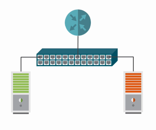
The port the router connects to is called the Promiscuous Port. Device ports are called hosts port. The Switch will allow host port to travel up on the promiscuous port to the default gateway on the Secondary isolated VLAN. Traffic from the Promiscuous port travels down the Primary VLAN to the host devices.
Hosts versus Promiscuous Ports
Traffic from a host port
Traffic from a host port traverses the secondary VLAN to reach a promiscuous port.
Traffic from a promiscuous port
Traffic from a promiscuous port traverses the primary VLAN to reach host ports.
Let’s configure Isolated VLANs
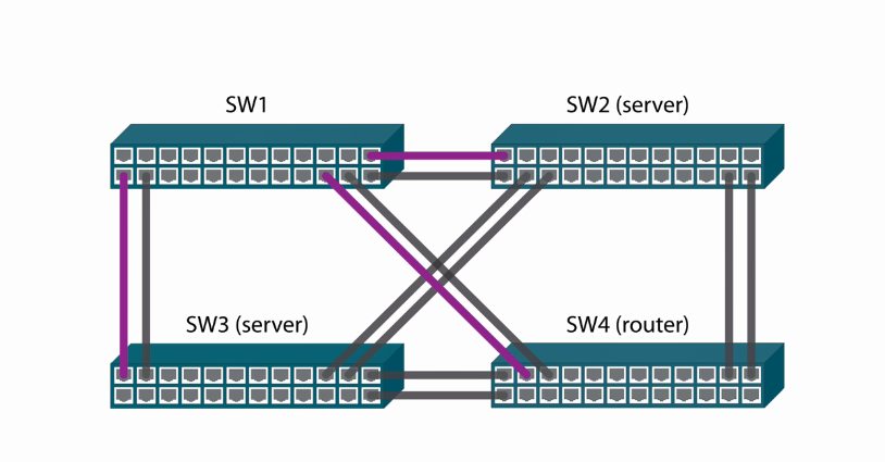
These interfaces are routed interfaces and not as switch access ports.
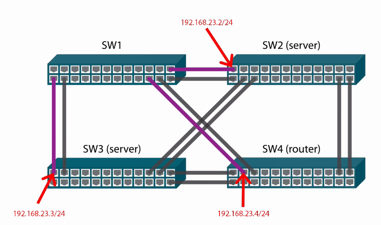
Let’s perform some configuration. Firstly et’s change the interface type to routed;
On Switch #2
SW2(config)#int fa0/1
SW2(config-if)#no switchport
SW2(config-if)#no switchport
Configure IP Address on the Switchport
SW2(config-if)#ip address 192.168.23.2 255.255.255.0
SW2(config-if)#no shutdown
On Switch #3
SW3(config)#int fa0/1
SW3(config-if)#no switchport
Configure IP Address on the Switchport
SW3(config-if)#ip address 192.168.23.3 255.255.255.0
SW3(config-if)#no shutdown

The address as you can see above is not assigned to a VLAN but to the routed interface.
On Switch #4
SW3(config)#int fa0/3
SW3(config-if)#no switchport
Configure IP Address on the Switchport
SW3(config-if)#ip address 192.168.23.4 255.255.255.0
SW3(config-if)#no shutdown

The address as you can see above is not assigned to a VLAN but to the routed interface.
Let’s look at a Requirement
Configure a Private VLAN domain as follows;
SW2 and SW3 should not be able to ping each other
SW2 and SW3 should be able to ping SW4.
On SW1 configure the Private VLAN
SW1(config)#vlan 223
SW1(config-vlan)#private-vlan isolated
SW1(config-vlan)#exit

SW1(config)#vlan 200
SW1(config-vlan)#private-vlan primary
Associate VLAN to Secondary VLAN
SW1(config-vlan)#private-vlan association 223
SW1(config-vlan)exit

SW1#show cdp neighbors

Let’s configure interface fa0/20 as promiscuous interface.
SW1(config)#interface fa0/20
SW1(config-if)#switchport mode private-vlan promiscuous
SW1(config-if)#switchport mode
Configure the Private VLAN Promiscuous Mapping

SW1(config-if)#switchport private-vlan mappingSW1(config-if)#switchport private-vlan mapping 200 223
Setup the Isolated Host Ports
SW1(config-if)#interface range fa0/2,fa0/11 SW1(config-if-range)#switchport mode private-vlan host SW1(config-if-range)#switchport private-vlan host-associationSW1(config-if-range)#switchport private-vlan host-association <200> <223> SW1(config-if-range)#do show private-vlan

Now that we have completed the configuration; let’s perform some tests from SW2;
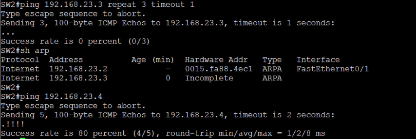
SW2#show arp

Perform tests from SW3
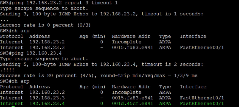
Perform tests from SW4

Show ARP on Sw4

So far this article has covered Understanding VLANS for CCNP Switch and to improve your knowledge in dealing with Community VLANs, click the link to learn more about Community Private VLANs.

