If you have ever wanted to know how to configure ip helper on a cisco switch for a number of vlans then this article may be the most helpful you might find regarding the appropriate steps required to successfully architect your desired network. The reason for such could be down to how your network has been designed hierarchically.
Let’s take a brief moment to breakdown the Hierarchical Design Model.
The Hierarchical Design Model architecture uses a hierarchical design model to break the design up into modular groups or layers. Breaking the design up into layers allows each layer to focus on specific functions which is what we would want our network to do, which simplifies the design and provides simplified deployment and management.
Imagine you have a junior network engineer who takes care of port security on the access layer, with a modular design t is easier to grant him the rights to perform the specific functions without the need for access to a hierarchy too advanced for his level of technical ability.
Another important reason for modularity in network design is that it allows you to create design elements that can be replicated throughout the network. Replication provides an easy way to scale the network as well as a consistent deployment method. In flat or meshed network architectures, changes tend to affect a large number of systems.
Hierarchical design helps constrain operational changes to a subset of the network, which makes it easy to manage as well as improve resiliency. Modular structuring of the network into small, easy-to-understand elements also facilitates resiliency via improved fault isolation.
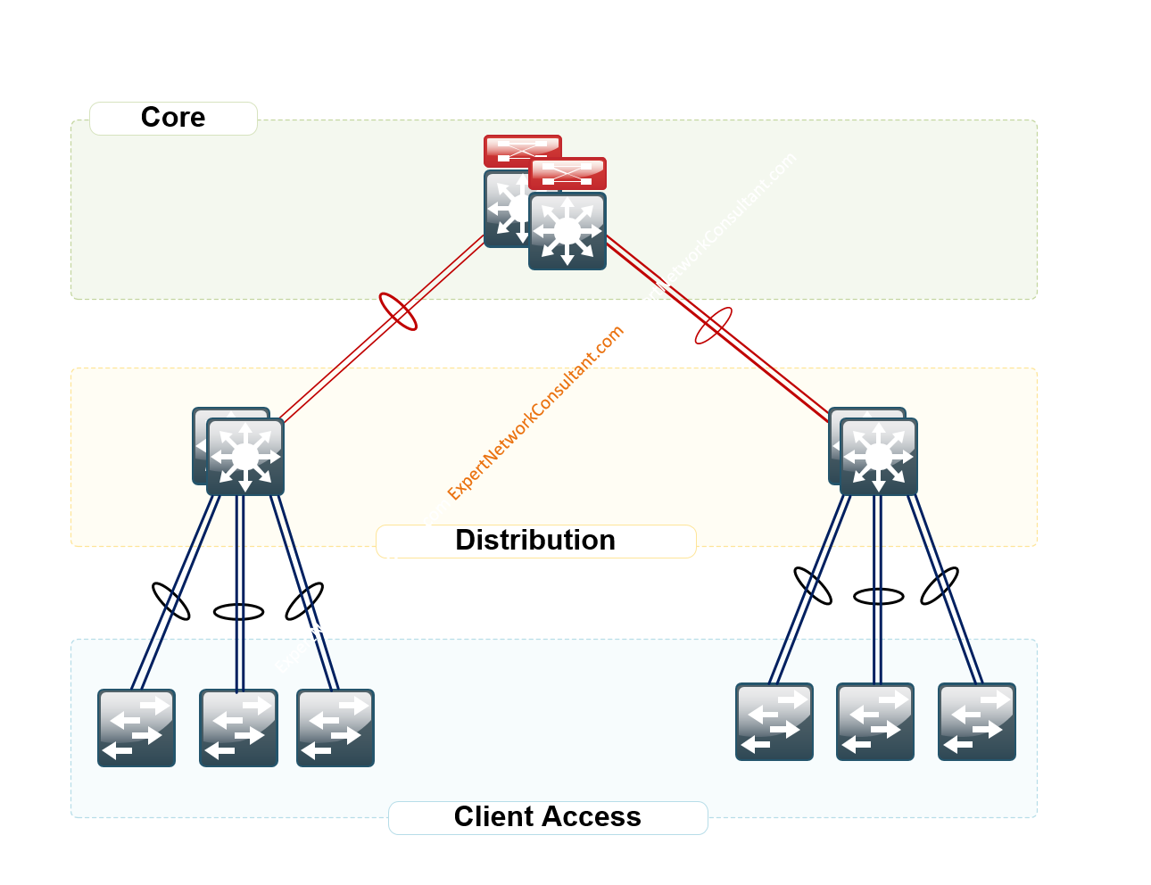
Figure 1.0 – LAN Hierarchical Design

A hierarchical design includes the following three layers:
• Access layer—Provides workgroup/user access to the network.
• Distribution layer—Aggregates access layers and provides connectivity to services.
• Core layer—Provides connection between distribution layers for large LAN environments
The beauty of this design is the ability to create redundancies and practical availability.
Observe the diagram in Figure 1.1 – Enterprise Campus Network (Two Tier Design: Distribution Layer functioning as a collapsed Core).
Figure 1.1
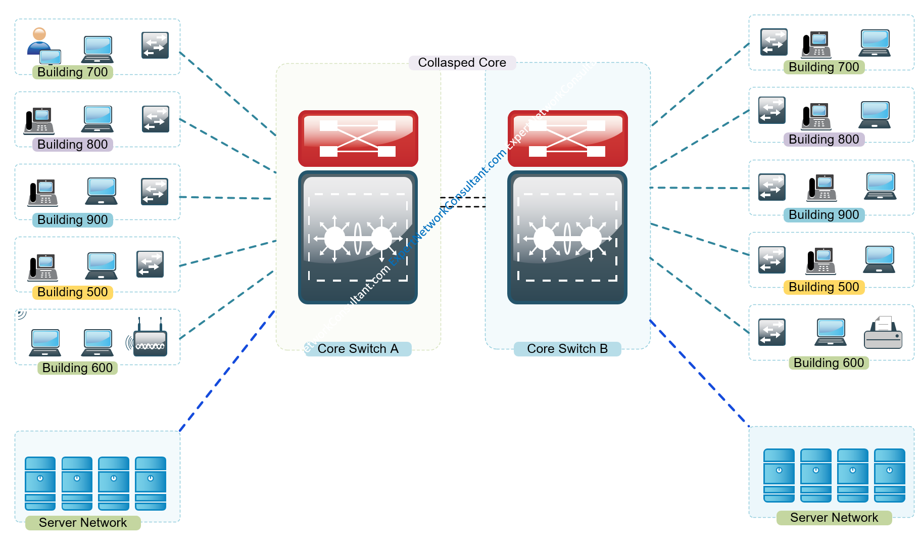
In a collapsed core network environment, your servers could be connected directly to your core or hang of a separate vlan off your core layer 3 switch as observed in the diagram above.
Now that we have covered the need for a hierarchical design, let us now dive in today’s discussion or post on how to configure ip helper on a Cisco switch for a number of vlans.
Network Equipment Used in our environment are as follows:
-
1. ASA 5506-X Firewall
2. Cisco Catalyst 2960 Series SI or
3. HP Aruba 48 PoE Switch
4. ISP Network Device
5. VMWare EXSi
6. Windows Server 2012 R2 Running DHCP Role
Why IP Helper
The reason for IP helper is the fact that many enterprises as per practice have always had a server taking care of their dhcp for the entire network. It is only wise to allow this function which is well versed and loved by server admins to remain. We also want the routers or switches on our network to perform the functions they are best at, i.e, Layer 2 and Layer 3 stuff.
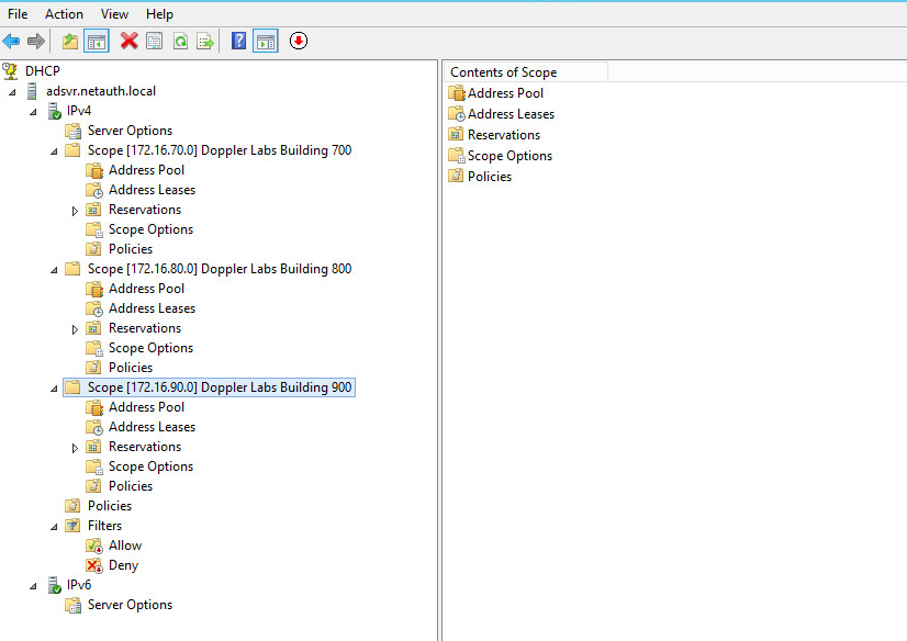
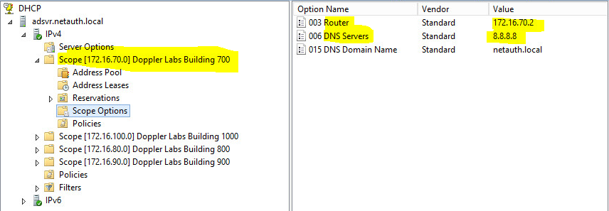
Below is a snippet from a DHCP Server Running Windows Server 2012 R2 . As you can see, there are a number of scopes designed with specific subnets to take care of each associated VLAN on the core switch.
For the sake of time, let us open the anatomy of Scope – Doppler Labs Building 700
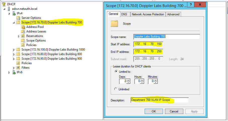
Scope Size: 172.16.70.150-250
DNS Server:8.8.8.8
Default Gateway: 172.16.70.2;
- I used 172.16.70.2 here as I had used on 172.16.70.1 on the the SVI for VLAN 700 on the Core Switch.
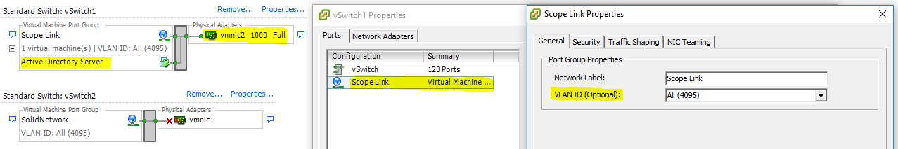
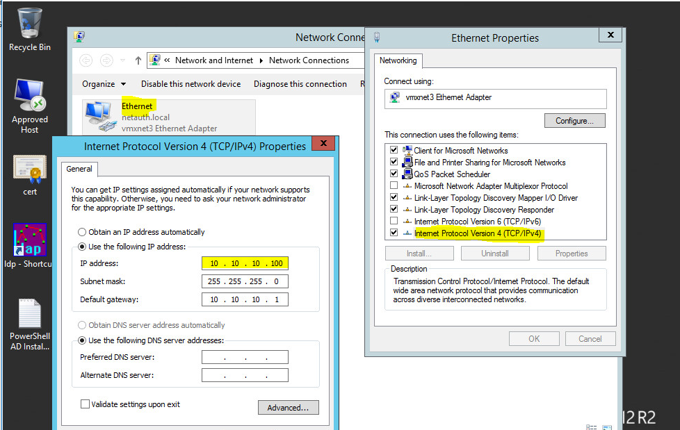
Settings for Network Interface Card on VMWare EXSi facing DHCP Server.
The Windows DHCP Server Configuration
VLAN Design Per Building
VLAN Name                             Status    Ports
---- -------------------------------- --------- -------------------------------
110  VLAN0110                         active    Fa0/40 [Interface Link to DHCP Server]
TRUNK INTERFACE                       active    Fa0/47 [Interface Uplink to ASA]


700  VLAN0700                         active    Fa0/1, Fa0/2, Fa0/3, Fa0/4
                                                Fa0/5, Fa0/6, Fa0/7, Fa0/8
                                                Fa0/9, Fa0/10, Fa0/11, Fa0/12

800  VLAN0800                         active    Fa0/13, Fa0/14, Fa0/15, Fa0/16
                                                Fa0/17, Fa0/18, Fa0/19, Fa0/20
                                                Fa0/21, Fa0/22, Fa0/23, Fa0/24

900  VLAN0900                         active    Fa0/25, Fa0/26, Fa0/27, Fa0/28
                                                Fa0/29, Fa0/30, Fa0/31, Fa0/32
                                                Fa0/33, Fa0/34, Fa0/35, Fa0/36
Step 1: Create a dedicated VLAN for the IP-Helper DHCP Server facing Network Interface
This is the interface which connects directly to the DHCP Server’s Network Interface Card which in our case is vmnic2 on the VMWare EXSi.
On Cisco
!
interface Vlan110
 description "Server VLAN"
 ip address 10.10.10.1 255.255.255.0
 end

!

interface FastEthernet0/40
 description "Link to DHCP Server aka IP-Helper"
 switchport access vlan 110
 switchport mode access
end
On HP Switch
vlan 110
   name "Server Facing VLAN"
   untagged 40 [Interface Connecting DHCP Server]
   tagged 47-48 [Carrying traffic across to other access switches where required]
   ip address 10.10.10.1 255.255.255.0
   exit
Configure Interface to the Firewall Inside Zone’s Interface
On Cisco
!
interface FastEthernet0/47
 description "Trunked Uplink Interface to ASA Inside Zone"
 switchport mode trunk
end
On HP
!
interface 47
 name "Uplink Interface to ASA Inside Interface configured as Trunk or Tagged"
 tagged vlan 700,800,900,1000
end
Step 2. Create VLANS for the Scopes Required
This step really is to have a dedicated VLAN for each department as per the diagram above. So in our case, consider the following buildings
On Cisco Switch
Switch#show run int vlan 700
!
interface Vlan700
 description Department 700 VLAN Scope
 ip address 172.16.70.1 255.255.255.0
 ip helper-address 10.10.10.100
 end
!


Switch#show run int vlan 800
!
interface Vlan800
 description Department 800 VLAN Scope
 ip address 172.16.80.1 255.255.255.0
 ip helper-address 10.10.10.100
 end


Switch#show run int vlan 900
!
interface Vlan900
 description Department 900 VLAN Scope
 ip address 172.16.90.1 255.255.255.0
 ip helper-address 10.10.10.100
!end
On HP Switch
vlan 700
   name "Department 700 Subnet"
   tagged 1,47-48
   ip address 172.16.70.1 255.255.255.0
   ip helper-address 10.10.10.100
   exit
vlan 800
   name "Department 800 Subnet"
   tagged 1,47-48
   ip address 172.16.80.1 255.255.255.0
   ip helper-address 10.10.10.100
   exit
vlan 900
   name "Department 900 Subnet"
   tagged 1,47-48
   ip address 172.16.90.1 255.255.255.0
   ip helper-address 10.10.10.100
   exit
Configure Cisco ASA 5506-X FirePower to Support Multiple VLANS Internet Access
As a good practice, I like to configure the Outside Interface or Zone on my firewall to ensure that it can readily speak to the Internet and so follow the breakdown below and configure your firewall the very same way but make sure you have identified the important IP Addressing Information pertaining to your ISP’s device.
ISP Internet Device’s Public IP: 192.168.1.1 1
route outside 0.0.0.0 0.0.0.0 192.168.1.1 1
Configure Network Interface to ISP’s Internet Device
!
interface GigabitEthernet1/8
 nameif outside
 security-level 0
 ip address 192.168.1.100 255.255.255.0
!
Configure DNS Settings;
dns domain-lookup outside
dns server-group DefaultDNS
 name-server 192.168.1.1
 name-server 8.8.8.8
 name-server 8.8.4.4
Enable ICMP Pings to Test Configuration Settings
access-list 100 extended permit icmp any any
access-list from_outside extended permit icmp any any echo
Firewall Inside Interface to CoreSwitch
!
interface GigabitEthernet1/1
 description "Interface Uplink to CoreSwitch"
 nameif inside
 security-level 0
 no ip address
!
Interface                  IP-Address      OK? Method Status                Protocol

GigabitEthernet1/1         unassigned      YES unset  up                    up

GigabitEthernet1/1.700     172.16.70.2     YES CONFIG down                  down
GigabitEthernet1/1.800     172.16.80.2     YES CONFIG down                  down
GigabitEthernet1/1.900     172.16.90.2     YES CONFIG down                  down
GigabitEthernet1/1.1000    172.16.100.2    YES CONFIG down                  down


GigabitEthernet1/8        192.168.1.100   YES CONFIG up                    up
Create Associated Sub-Interfaces
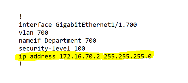
!
interface GigabitEthernet1/1.700
 vlan 700
 nameif Department-700
 security-level 100
 ip address 172.16.70.2 255.255.255.0
!

!
interface GigabitEthernet1/1.800
 vlan 800
 nameif Department-800
 security-level 100
 ip address 172.16.80.2 255.255.255.0
!

!
interface GigabitEthernet1/1.900
 vlan 900
 nameif Department-900
 security-level 100
 ip address 172.16.90.2 255.255.255.0
!
Create Object Groups and NAT for the required Subnets;
object network Department-700
 subnet 172.16.70.0 255.255.255.0
 nat (Department-700,outside) dynamic interface
object network Department-800
 subnet 172.16.80.0 255.255.255.0
 nat (Department-800,outside) dynamic interface
object network Department-900
 subnet 172.16.90.0 255.255.255.0
 nat (Department-900,outside) dynamic interface
How about getting devices on separate vlans to communicate? On the ASA, configure a dhcprelay as the dhcp scope sits on a separate server;
dhcprelay server 10.10.10.100 outside
dhcprelay enable inside
dhcprelay setroute inside
How about giving a go with Configuring a Guest WiFi with VLANS ?